Smith-Putnam Industrial Photos
These industrial photos of the construction of the Smith-Putnam wind turbine came into my possession in the 1970s. Carl Wilcox gave me a box containing these photos and other artifacts after I had interviewed him about his work with Palmer Putnam and the Smith Company. Carl lived in York, Pennsylvania where the Smith Hydro Company had been located. I lived nearby at the time in the state capital of Harrisburg.
Since I first posted scans of these images many years ago, the documentation on the Smith-Putnam project has grown substantially. The York County History Center has an extensive collection of materials on the project, including a scale model. The University of Massachusetts at Amherst (UMass) also has a collection of archival materials.
Here are some links to further information on the project.
- Smith-Putnam Wind Turbine Virtual Exhibition Goes Live
- Smith-Putnam Turbine: Patents and Movie Clip
- Carl Wilcox’s Role in the Smith-Putnam Project
- Smith-Putnam Wind Tunnel Tests
- Brief Movie Clip of the Smith-Putnam Turbine in Operation (at 3.10 minutes)
- Palmer Putnam’s 1.5 MW Wind Turbine Video, Engineering and Technology Wiki
- Harnessing the Wind Time Magazine, Monday, Sep. 08, 1941 (behind paywall)
- Oct. 19, 1941: Electric Turbines Get First Wind, Wired Magazine, October 19, 2009
- The Story of Grandpa’s Knob: How Vermont made wind energy history, VermontBiz, October 24, 2013
- A Bold Effort in Vermont: The 1941 Smith-Putnam wind turbine by Carl Sulzberger
- New Smith-Putnam Records Uncovered Include Log Books
- World’s Largest Wind Turbine Plant Nears Completion
- The Smith-Putnam Wind Turbine reprinted from Turbine Topics June 1943
If anyone has information or details on the project not found in Palmer Putnam’s book or in the captions, please contact me and I’ll update this page.
Note. To my knowledge these photos are in the public domain. I claim no copyright on them. I will provide high-resolution versions of these images upon request. I ask only that the photos be identified with “Photos from the collection of Carl Wilcox.” The prints and negatives are now in the possession of the York County History Center in York, Pennsylvania.
Note. The York County History Center in York, Pennsylvania has uncovered records, log sheets, shop models and photos in its collection.
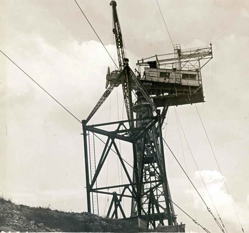
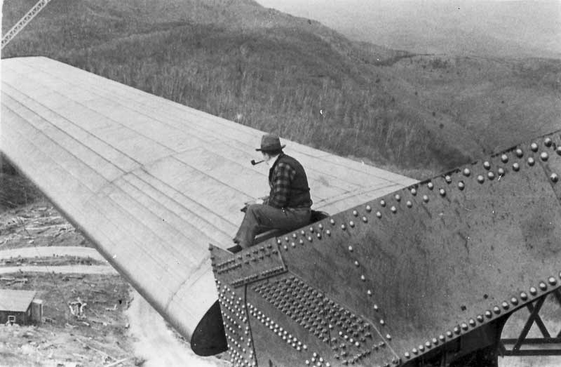
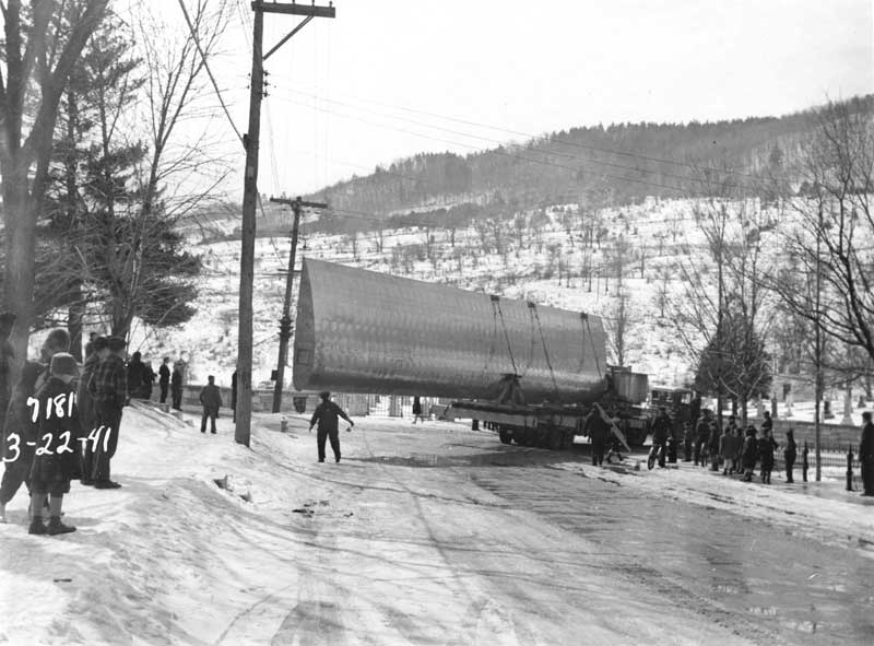
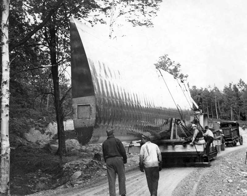
The Smith-Putnam wind turbine was the largest in the world until the Mod series of machines in the 1980s in the USA, Growian in Germany (1983), and Tvindkraft in Denmark (1978). The turbine was installed atop Grandpa’s Knob near Rutland, Vermont in the early 1940s.
Here’s what I had to say about it in my 1995 book.
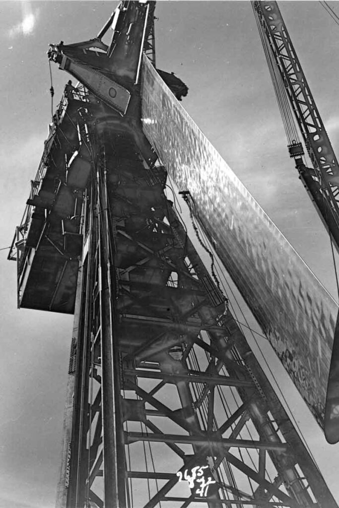
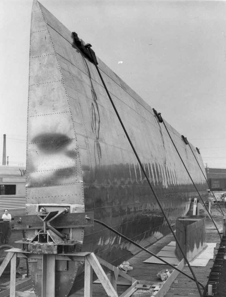
“. . . Both styles of development can be traced to World War II. On one side of the Atlantic, Palmer Putnam assembled a talented team of engineers and academics to build a giant wind turbine 53 meters (175 feet) in diameter for the S. Morgan Smith Co., a manufacturer of hydroelectric turbines. The 1.25 MW Smith-Putnam turbine became a technological guidepost pointing the way to subsequent American downwind designs of large wind turbines. . .
Note: The wind turbine is more correctly identified as a 1 MW and not 1.25 MW as Putnam described it.
See When is a 1,250 kW Wind Turbine Only 1,000 kW? Setting the Smith-Putnam Record Straight for why this is the case.
See Beating a Dead Horse–More on Smith-Putnam’s 1,000 kW Rating
See Confirmed: Tvindkraft Designed to be Slightly Larger than Smith-Putnam
“. . . In contrast to Juul’s measured development and Hütter’s use of previous wind turbine experimentation, Putnam, with no prior experience, leaped from the small battery-charging machines then in use on the American Great Plains to a multi-megawatt machine. Of the three, Putnam was the most unsuccessful. His machine threw a blade in 1945 and was dismantled. Only dusty photos remain of Putnam’s bold effort. . .”
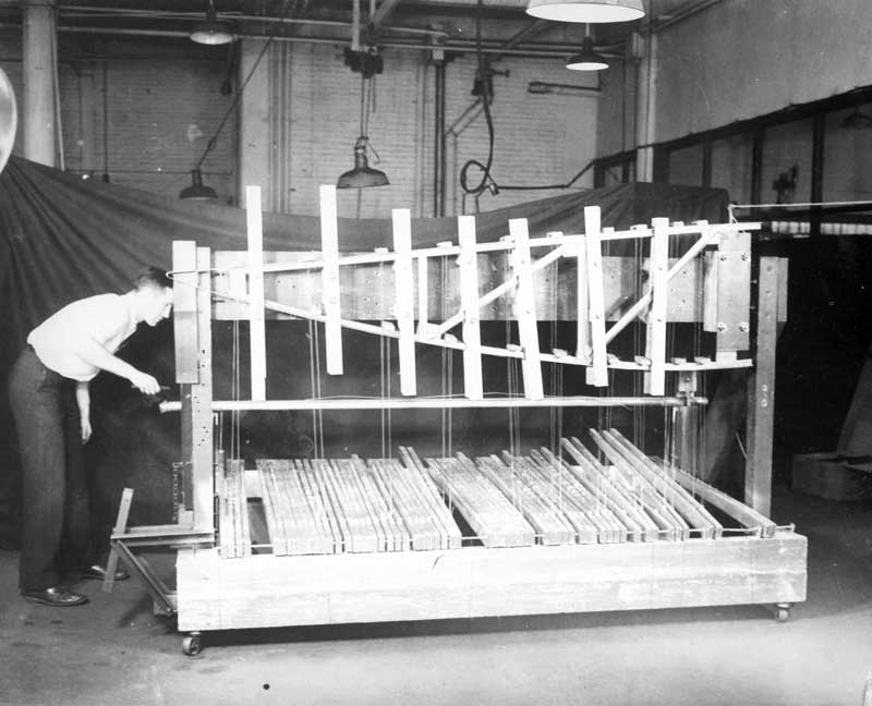
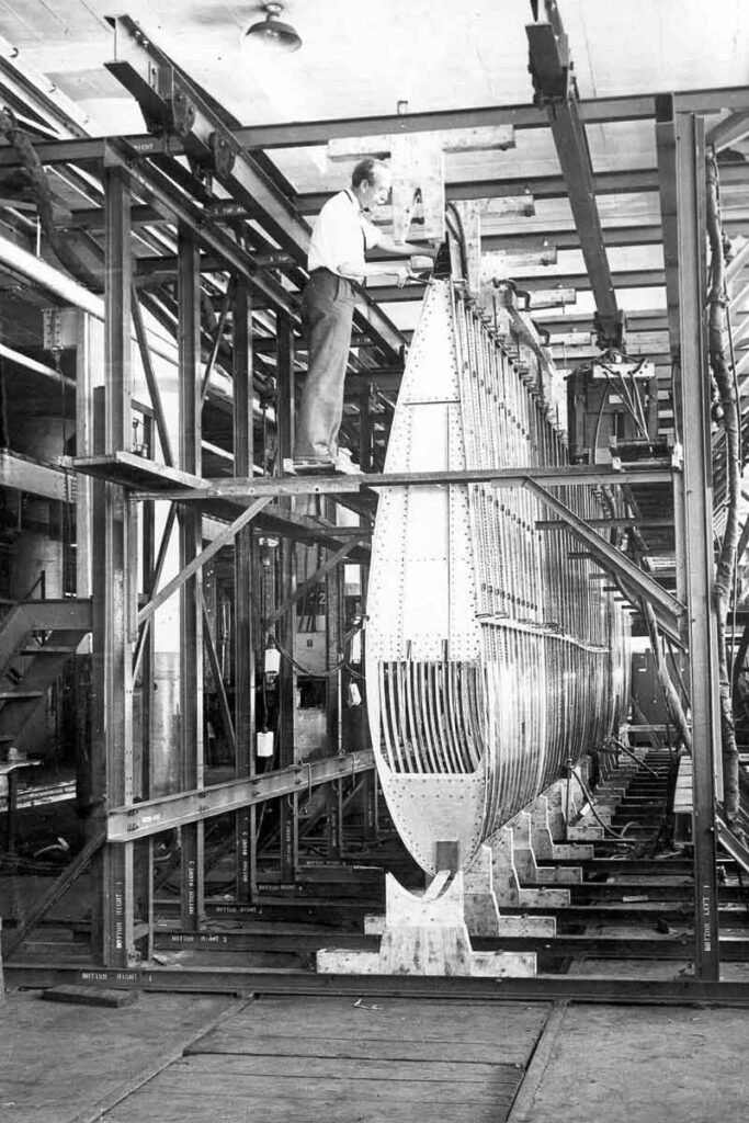
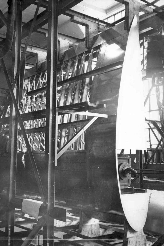
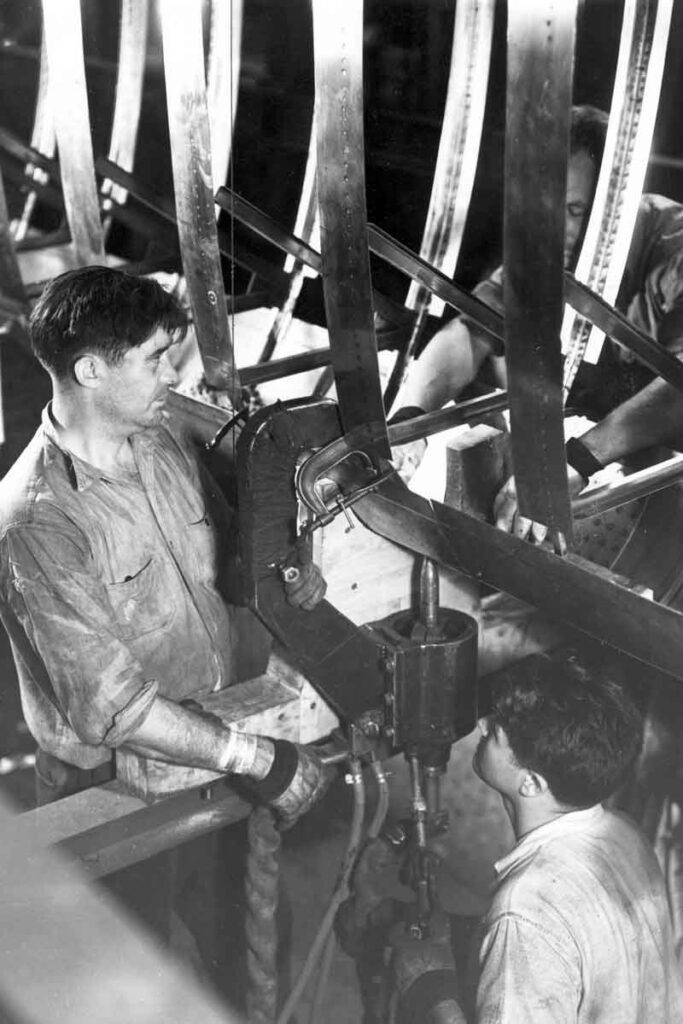
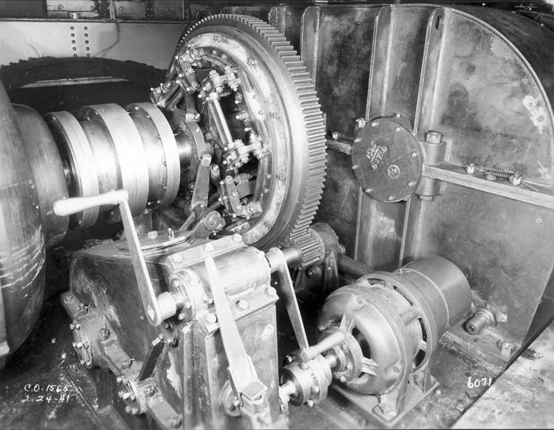
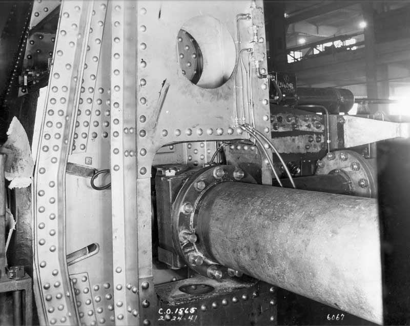
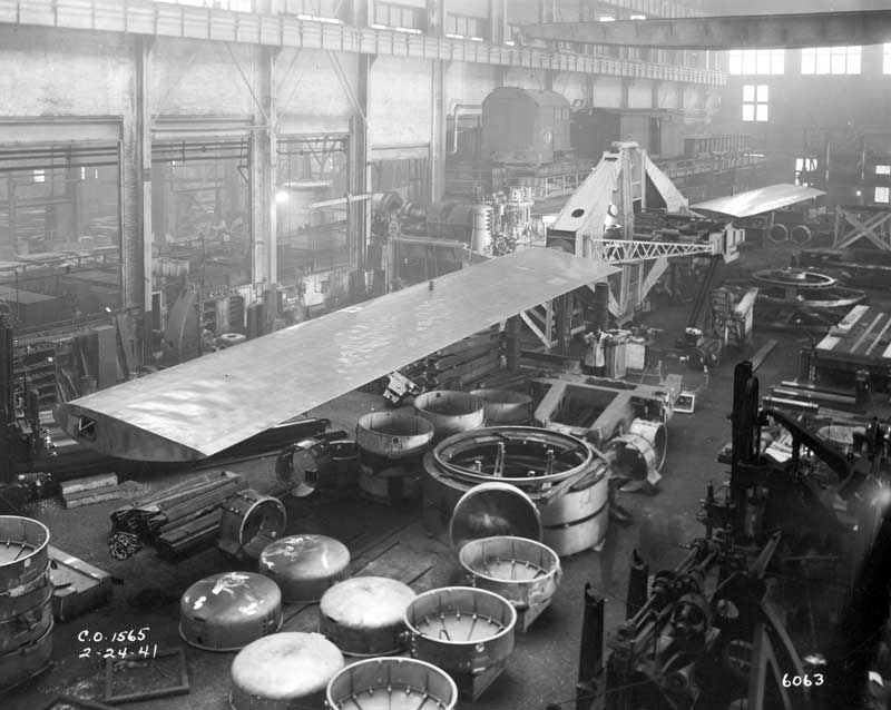
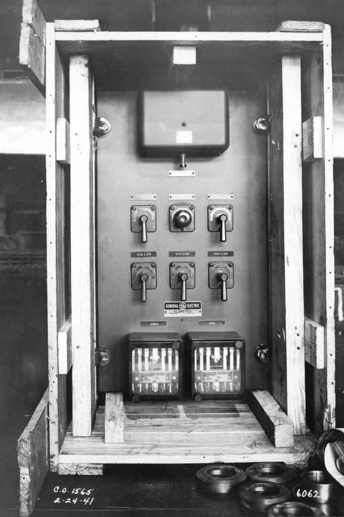
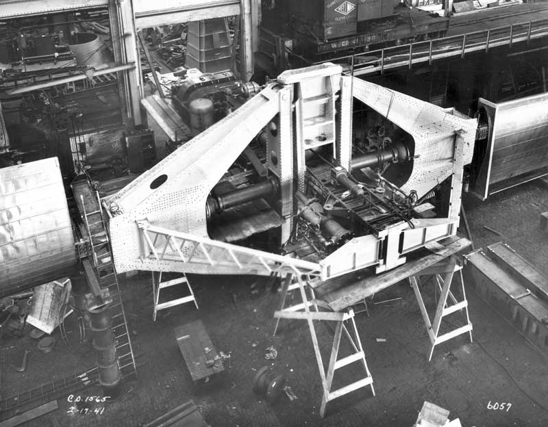
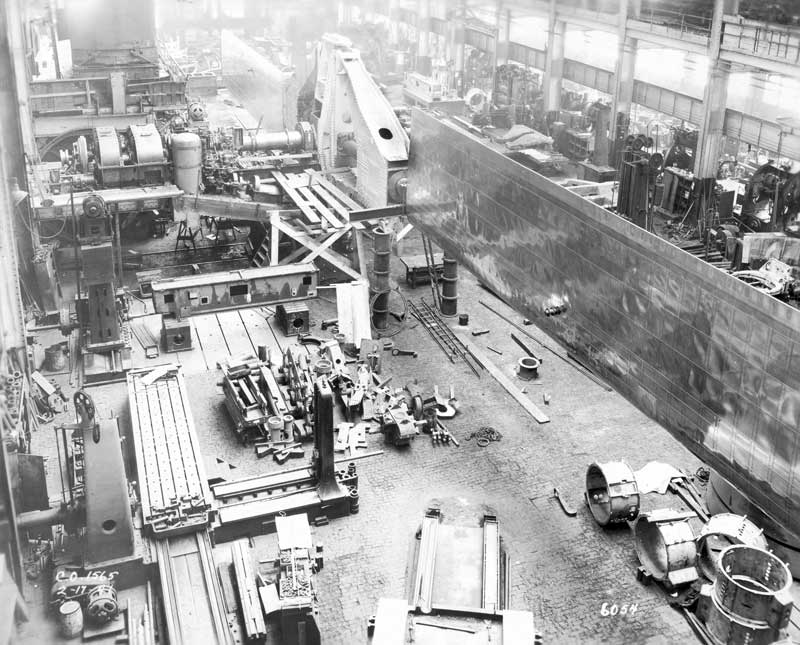
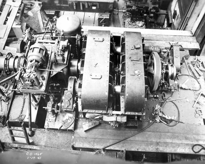
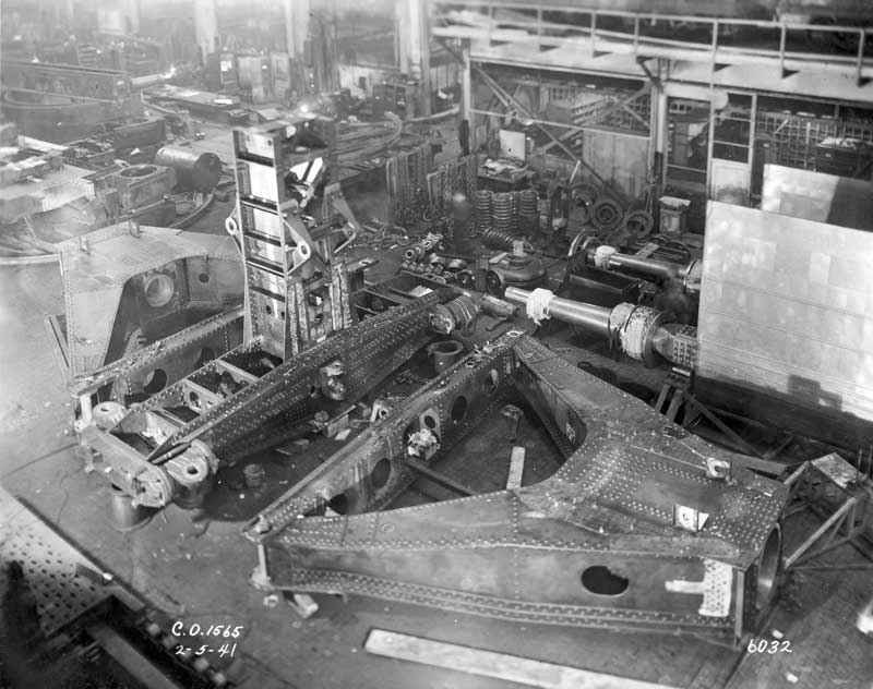
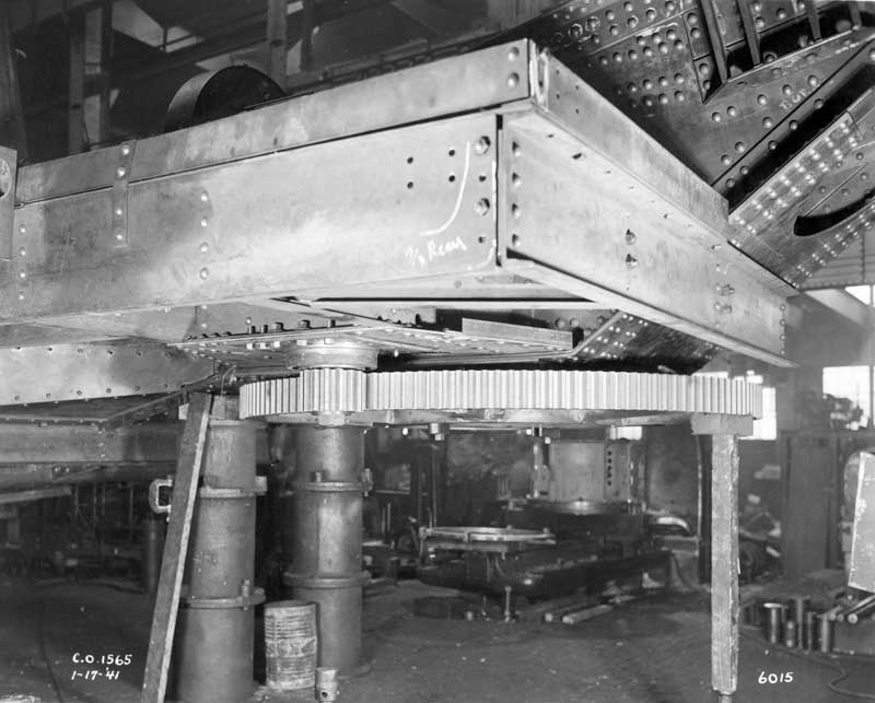
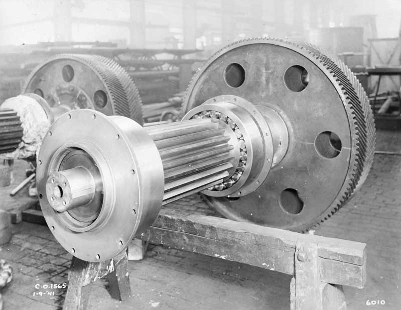
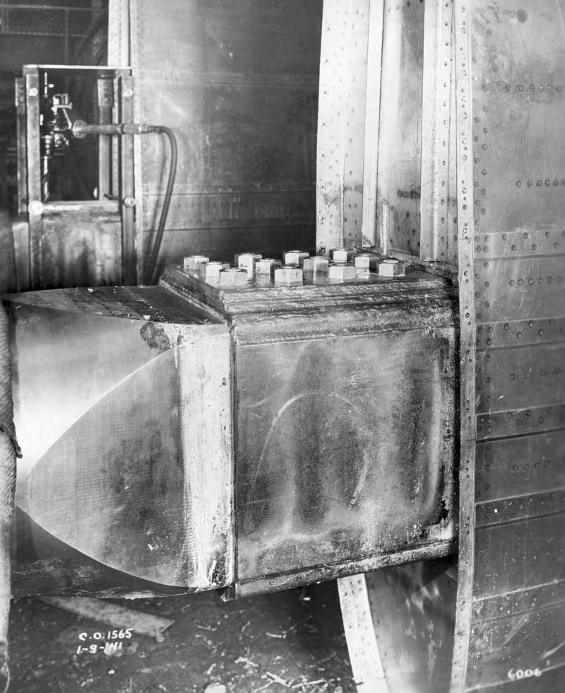
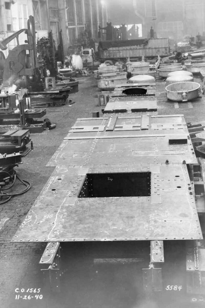
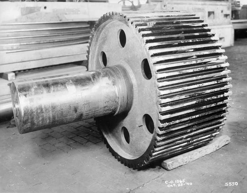
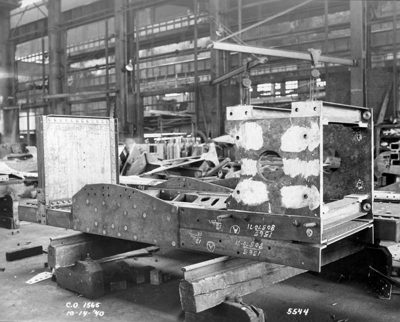
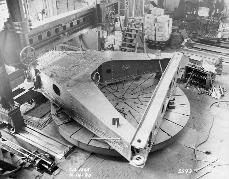
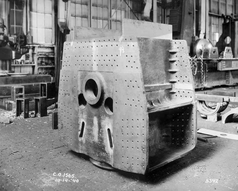
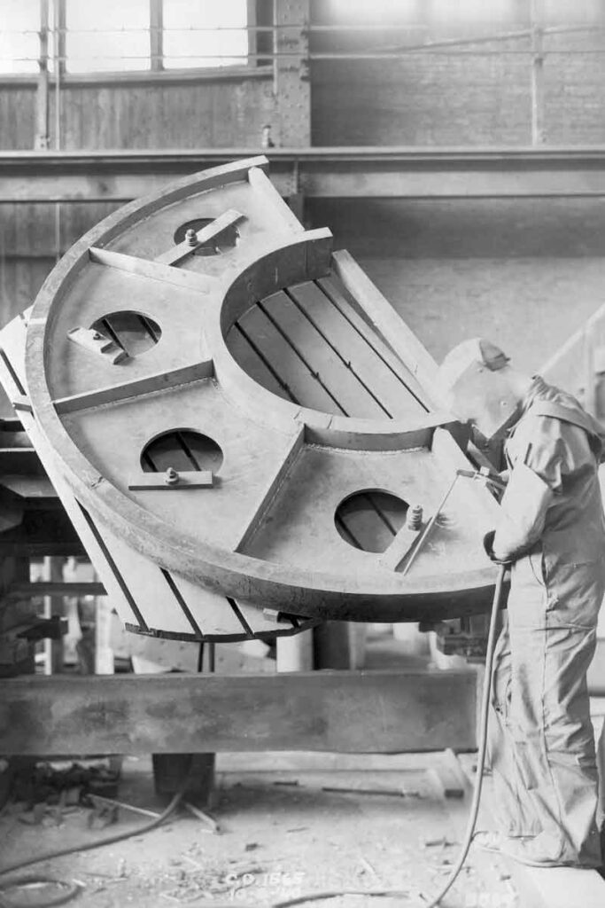
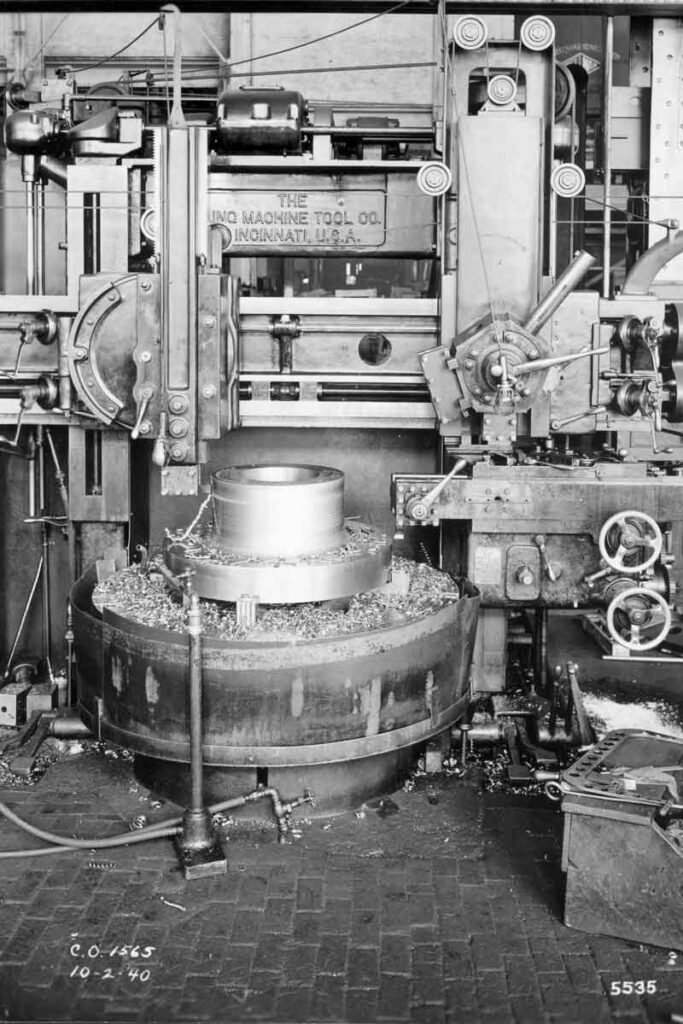
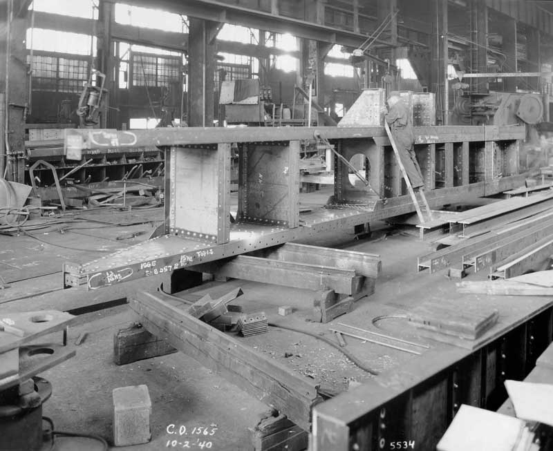
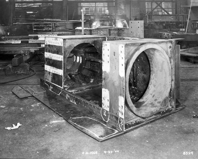
The photos below were glued to leaves in a large format album. Each is numbered. With the exception of those obviously in Vermont, the photos were likely taken in either the Budd Co.’s shop near Philadelphia or the Smith Co.’s plant in York.
My thanks to Howard Mayo of York, Pennsylvania for the photo captions below.
Howard Mayo’s family was closely connected to the Smith-Putnam project. Howard’s father negotiated the contract with Central Vermont, the local utility, for the delivery of the electricity from the turbine. His mother took a 16 mm film of the project, a portion of which was used by General Electric in a recent advertising campaign. Howard himself presented a prescient technical paper in 1945 predicting that if the wind turbines were built by the hundreds and located along mountain ridges with remote control and scheduled maintenance they might become economical.
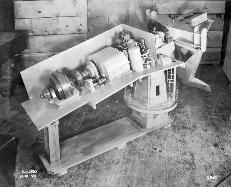
Howard donated the two wooden models of the Smith-Putnam turbine that were in his family’s possession to York’s Heritage Trust Museum. The museum also houses files on the Smith-Putnam turbine, including the files of Carl Wilcox.
Photo montage of the Smith-Putnam Wind Turbine ready for testing at Grandpa's Knob, Vermont. This 1000 kW unit with 175 foot diameter of blade tips was the world's first megawatt-size wind turbine in 1941. Photo by Grant H. Voaden, Assistant Chief Engineer for the project.
View of Wind Turbine tower, blade and generator platform from the ground with the erection crane boom on the right. Tower 110 feet high, weight 125 tons, weight aloft 240 tons. Tower was erected by American Bridge Co. of Ambridge, PA.
Smith-Putnam photos. Erection crane lifting generator platform in preparation to lowering onto pintle presumably on a windless day.
Smith-Putnam photos. Completed support tower with generator platform and housing attached. Erection crane frame is in foreground with boom extending skyward.
Smith-Putnam Photos. This photo was sent by Mike Lawson, York County History Center, to Jim Manwell at UMass.
Smith-Putnam Photos. This photo was sent by Mike Lawson, York County History Center, to Jim Manwell at UMass. Lawson believes this is Palmer Putnam sitting on the blade.
Smith-Putnam Photos. Main shaft with up-wind main bearing and Oldham coupling in foreground.
Smith-Putnam photos. A completed Wind Turbine blade loaded for shipment. Dent in end appears to be accidental damage.
Smith-Putnam Photos. Fixture used for checking alignment of individual blade sections prior to application of skin plates.
Smith-Putnam photos. Internal plates help stiffen the Wind Turbine blades and transmit the wind load to the box girder.
Smith-Putnam Photos. Wind-turbine blade shape and internal bracing was very similar to that of an airplane wing.
Smith-Putnam photos. Jig facilitates continual checking of blade straightness and curvatures as assembly progresses.
Smith-Putnam photos. Skeleton assembly of blade showing internal bracing and box girder that transmits wind load to A-frame.
Smith-Putnam photos. Partial assembly of skin plates onto skeleton frame of blade viewed from trunnion end.
Smith-Putnam photos. Assembled blade viewed from trunnion end showing airfoil shape.
Smith-Putnam photos. Workmen at Budd Manufacturing Co. working on a blade skeleton.
Smith-Putnam Photos. Turning from the main road onto the construction road required careful attention to the blade overhang to miss utility poles.
Smith-Putnam Photos. Another view of Wind Turbine blade mounted on a flat bed trailer with anemometer mast, crane and tower in background.
Smith-Putnam Photos. Hauling one blade up the construction road to the installation site required great care.
Smith-Putnam Photos. Stanton Dornbirer briefing Palmer Putnam manager of the Smith-Putnam Wind-Turbine Project in the Boston, MA office of S. Morgan Smith Co. at 176 Federal Street.
Smith-Putnam Photos. Far side of blade positioning gear with motor driven pinion gear and manual cranks in front of flexible coupling.
Smith-Putnam Photos. Blade positioning gear with both motor or manual drives on far side. On right is flexible coupling before hydraulic coupling.
Smith-Putnam Photos. Pivoted hydraulic cylinder used to dampen coning of blades due to wind gusts. Located on both sides of tail piece.
Smith-Putnam Photos. Close-up view of flange connection to torque tube for adjusting blade pitch angle.
Smith-Putnam photos. Torque tube for changing blade pitch within A-frame which permits coning the blades.
Smith-Putnam Photos. Looking up-wind from blades, governor pressure tank in middle with oil pump and motor at top right over governor.
Smith-Putnam photos. Governor oil piping and isolation valves by Woodward Governor Co., Rockford, IL.
Shop assembly with blades faired and A-frames on the right side of picture.
Smith-Putnam photos. Switchgear cabinet with local control switches by General Electric Co.
Smith-Putnam Photos. Generator platform shop assembly with down-wind main bearing on left, main shaft, up-wind main bearing under governor oil pump and motor and speed increaser on right.
Smith-Putnam Photos. A- frame assembly from an up wind angle with one blade attached. Coning link truss construction is clearer.
Smith-Putnam Photos. A-frames assembled on shop floor with coning cylinders on each side of center extension.
Smith-Putnam Photos. Shop assembly of both blades, A-frames, shaft, bearings, gear box and generator, with shaft horizontal.
Smith-Putnam Photos. View from above A-frame assembly with center drive box section, main shaft and down-wind main bearing.
Smith-Putnam Photos. View from above with motor driven governor oil pump on left, speed increaser in middle and generator on right.
Smith-Putnam Photos. Wind Turbine blade from outer end. Shop assembly with A-frames and coning dampening mechanism.
Smith-Putnam Photos. Smith-Putnam Wind Turbine model side view shows hydraulic cylinder under extension off A-frame cross arm. Speed increaser is shown as a single housing with hydraulic coupling before the generator.
Smith-Putnam Photos. A-frame prior to assembly with drive cross arm on shop floor. Two blades in background, with shaft extensions and universal joint.
Smith-Putnam Photos. Fabricated steel speed increaser housing from low speed drive end. Auxiliary drive gear is beside the coupling flange.
Smith-Putnam Photos. Partial shop assembly of generator platform with main shaft, down wind main bearing, upwind main bearing and Woodward governor pressure tank.
Smith-Putnam photos. Upper section of support tower with pintle extending from the top.
Smith-Putnam Photos. Outboard bearing on blade shaft adjacent to blade box girder connection.
Smith-Putnam photos. Shop assembly of the upper section of the support tower with access walkway.
Smith-Putnam Photos. Generator platform from below showing yawing pinion and adjacent large drive gear operated from above by an hydraulic motor.
Smith-Putnam Photos. Low speed bull gear directly connected to main Wind Turbine shaft half coupling.
Smith-Putnam Photos. Pinion gear supported by wood horse with bull gear directly connected on right.
Smith-Putnam Photos. View from under side of generator platform with pintle extending forward to left. Bearing surface has lagging protection.
Smith-Putnam Photos. Generator platform on one side viewed from top with upper end of pintle showing in foreground.
Smith-Putnam Photos. Final connection between blade box girder and torque shaft.
Smith-Putnam Photos. Temporary clamps holding Wind Turbine box girder to torque shaft during alignment adjustments and checks.
Smith-Putnam photos. Platform assembly on the weld shop floor at S. Morgan Smith Co., York, PA.
Smith-Putnam Photos. Wind Turbine model from generator platform end. On left is generator then hydraulic coupling and gear-box / speed increaser. Then governor oil pressure tank and piping before upper support tower with railing.
Smith-Putnam Photos. Wind Turbine model showing a blade stub, A-frame with support, shaft extension with link to A-frame, upper tower section with access walkway and generator platform on right with model base and platform support.
Smith-Putnam Photos. Spur gear in shop prior to assembly in housing.
Smith-Putnam Photos. Two Wind Turbine blades on temporary shop supports prior to shipment to Vermont.
Smith-Putnam Photos. Wind Turbine shaft on horizontal planer. This appears to be an unusual use for a planer, possibly necessitated by machine tool loads.
Smith-Putnam Photos. Lower half of fabricated steel three stage speed increaser. Input about 28.7 RPM and output up to 625 RPM with a gear ration of about 1 to 21.
Smith-Putnam photos. Internal machining of coupling on a horizontal boring machine.
Smith-Putnam photos. Welded box structure with white washed areas to facilitate drill hole layout with scribed lines.
Smith-Putnam photos. A-frame resting on boring mill table. Likely for temporary storage.
Smith-Putnam photos. Welded plate steel housing with extensions pre drilled for rivets.
Smith-Putnam photos. Welding one half of a tower flange mounted on a welding positioner.
Smith-Putnam photos. Machining one half of a shaft coupling on a vertical boring mill.
Smith-Putnam photos. Generator platform on one side in shop. Probably took up less room.
Smith-Putnam photos. Shop assembly of upper section of support tower which contained the thrust bearing and pintle support.
Smith-Putnam photos. Installing shaft into housing with crane support plus two men lifting end and one pushing or pounding.
Smith-Putnam photos. Riveted construction assembly was complicated, time consuming and expensive.
Smith-Putnam photos. Completed sub assembly with riveted construction necessitated by War time constraints on use and supplies of weld rods.
Smith-Putnam photos. Huge open-end wrench lifted by shop crane. Where and how this wrench was used is unknown at present.
Smith-Putnam photos. Blade coning A-frame viewed from the side while assembled with the shaft axis vertical.